-40%
MK II 12V 3A Dual Single Axis Solar Panel Sun Tracking Electronic Control Board
$ 15.83
- Description
- Size Guide
Description
Welcome to Hobbiz Electronics.Home
About us
Returns
Delivery
Contact Us
HAVE A QUESTION? -
Click to find out more
Feedback
Add to Favorite Seller
Join Mailing List
CATEGORIES
Home
Metal Detectors
Solar Panel Sun Tracking Cntrl
Proto Breadboard
New Arrivals
Others
FAST AND FREE
SHIPPING ON SOME OF THE ITEMS
Trusted Store
USA Seller & Secure Packaging
30 Days
Money Back Guarantee
Product information
MK II Dual or Single Axis Solar Panel Sun Tracking Tracker Controller Boards DIY - 12VDC 3Amp
Click on the Image to Enlarge
Specification:
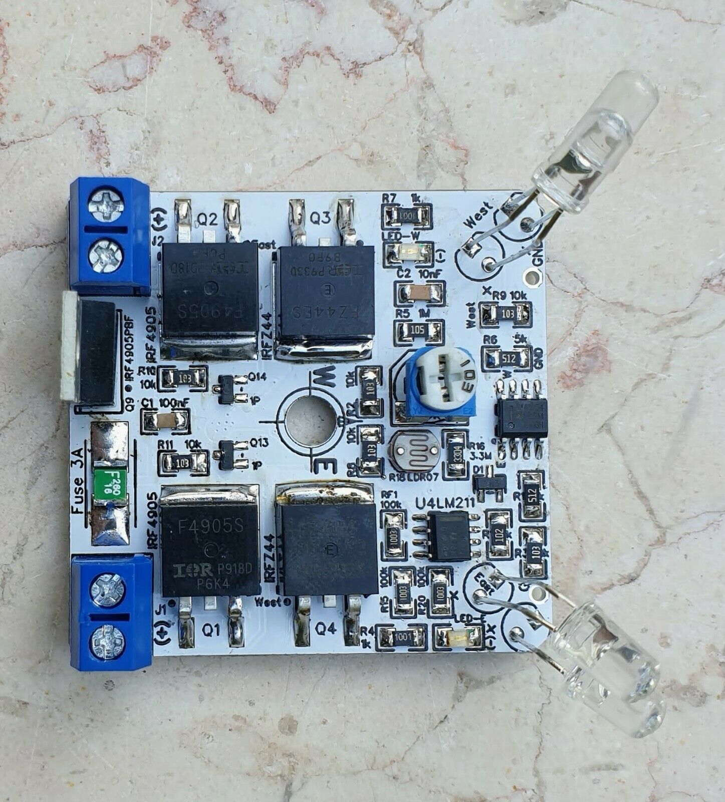
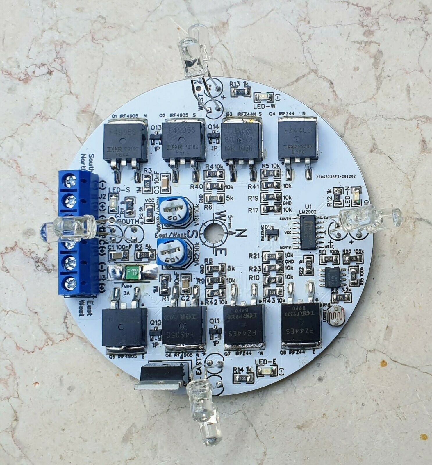
Dual or Single Axis Sun Tracking Controller Boards
Resetting Self-Recover Fuse for electrical short/over current protection
Auto West to East Sensor at Nigh
Optimize your energy harvesting to increase it by up to 30%
Operating Voltage: DC 12V±20%
Protect your controller during installation/maintenance - Full Reverse Voltage Protection
Drive Current: 1.5 Amp, 2 Amp Peak (with load)
Operating Temp: Extended Industrial Grade LM2904/2902 family : -40[℃] to +125[℃]
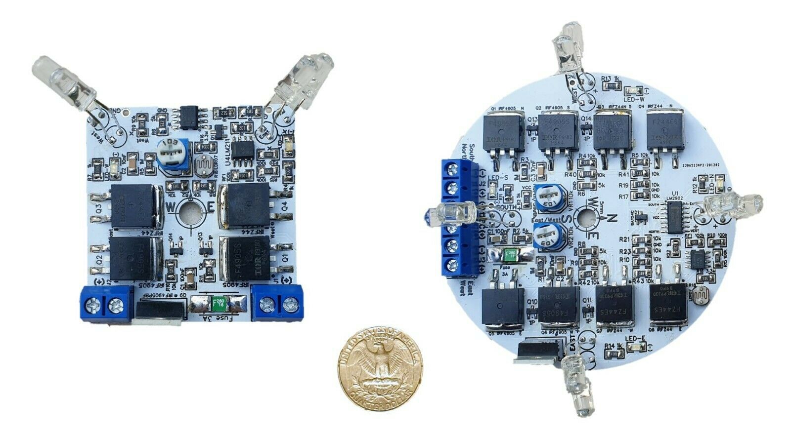
The MK II Controller Board compact design can be installed in a 150mil Jar with 81mm/3.2in inner diameter
The Enclosure/Dome is not included
Please visit my Store for a Jar Enclosure (made from PET) Kit
Description
MK II 12VDC 3Amp Dual or
Single
Axis Enhance Solar Panel Sun Tracker Controller Boards
for DIY projects
1.
MK II Controllers Arrived
Dual or Single Axis
MK II
Design Features
New Features
1.
Resetting Self-Recover Fuse
for electrical short/over current protection
2.
Auto
West to East Sensor and Night, Return automatically to east after the sunset
Common Features
1.
Reverse
Voltage Protection
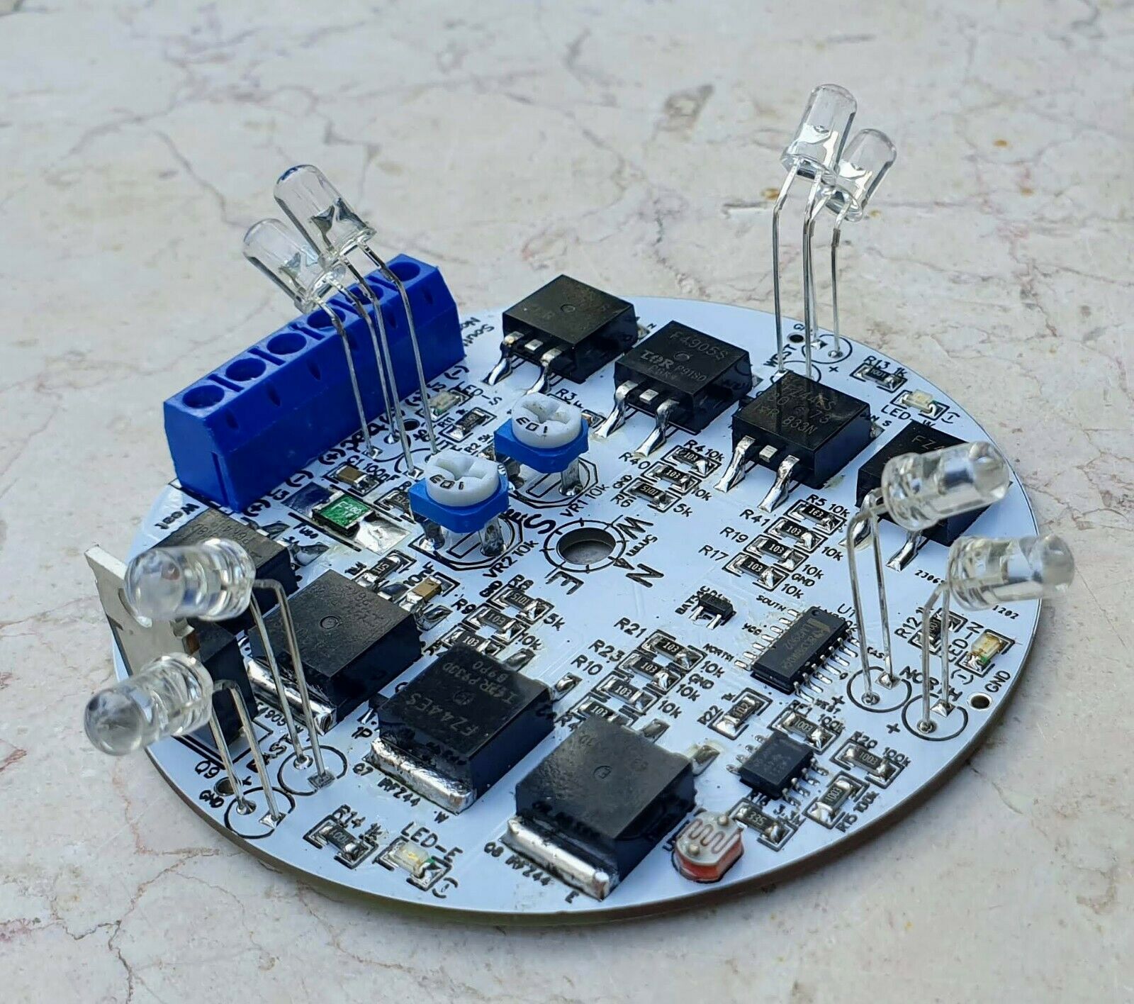
2. LED indicators for each direction
3. Taller Water Clear 5mm LEDs
4.
Improve efficiency using complementary N and P MOSFET channels to eliminate self heat dissipation under load
5. No Need for heat sink, simplify the assembly and design
6. Thicken the main leads to be at least 1mm/0.04in up to 2mm/0.08in, better durability to high current
7. Smaller form factor to fit to a smaller dome case
8. Specially design to fit to a 150mil Jar with 81mm/3.2in inner diameter
*Note: Please see FAQ paragraph # 10 for common questions and answers
Mark II Sun Tracking Controllers arrived. These controllers are the best analog controllers until now with new innovative features. Better protection with over current and reverse voltage. Improved energy harvesting efficiency, now with built-in auto west to east sensor at night. Multiple flavors, e.g. Dual Axis, Single Axis, 12VDC3A, 12VDC10A, 24VDC10A etc... All in a compact form factor can be fitted into a Jar, Dome, or Small Enclosure for weather protection. In my eBay Store you can also find a variety of accessories that are added to existing systems, like Relay Modules, Wireless Controllers, Sensors etc...
Solar PV Panel Sunlight Tracker Controller advance technology, SMD low profile components, compact size, solid state high power MOSFETs. Required for hobbies, DIY projects, sunlight tracking, high quality etc... I'm using one from my own design at my garden, see pictures and movie clip.
I designed and fabricated this controller as a lesson learnt from my Solar Panel DIY project. I used controller for dual axis that I purchased on line, two of them actually stopped operating after several months mainly due to overheating causing the leads to "melt". In my design I added thick traces for the power lines, and SMD MOSFETs with multiple via holes between the two layers for better cooling. I also selected a comparator chip for extended temperature and made the PCB covered with white solder mask that should reduce a little bit the internal heat due to direct sunlight. I'm offering the controller with relatively comfortable price to the benefit of DIY hobbyists like me.
The design support dual axis, i.e. the board with dual sun tracking control East/West
and
North/South for the southern and
northern
hemisphere
.
The sun tracker controller is supporting the most common application of 12VDC +/-20% from a battery, or any other power supply source. If you need 24VDC please see other listing in my eBay store.
The controller uses H-Bridge that drives the motor in either direction, i.e. clockwise/anticlockwise, left/right or up/down according to the sun location. The controller
do
reposition
for the morning sunshine automatically at night, it uses a dedicated west to east sensor on board. The design can work with only one LED, I put two LEDs for each compass direction to allow more flexible field of view since these LEDs have narrow angle field of view for better precision. Using the LEDs one can catch more field of view mainly due to
clouds
or other reasons that my block the sun, i.e. skew lightly the LEDs such that each LED will cover more angle, this will ensure smoother operation.
Please visit my
Youtube
Channel to see it working, URL:
https://youtu.be/f_Z05bQw1kI?list=PL9n6C-MsF_W1AVWEN5f6w1MnkDQShryZh
You may like my other listing:
DIY Proto Breadboard PCB White or Yellow:
https://www.ebay.com/itm/333234608146
DIY Proto Breadboard PCB with Proto Build of H-Bridge Project:
https://www.youtube.com/watch?v=YdZrKbVN09c&feature=youtu.be
Visit my eBay Store HobbizElectronics
http://www.ebaystores.com/hobbizelectronics
DIY Sensors Board Module:
https://www.ebay.com/itm/333405257471
DIY Single High Current Module:
https://www.ebay.com/itm/333396177143
DIY Heat Temp Module:
https://www.ebay.com/itm/333409364670
DIY Dark Light Module:
https://www.ebay.com/itm/333409321972
DIY
Auto
West East Sensor
:
https://www.ebay.com/itm/333728647371
DIY Dual High Current Module:
:
https://www.ebay.com/itm/333554217949
2. Parameter
#
Parameter
Value
1
Name
Single or Dual Axis Sun Tracker Controller Board
2
Operating Voltage
DC 12V±20%, voltage source can be for example a car battery, Power Supply etc…
3
Operating Current
15 mA (no load)
4
Standby Current
1 mA (no load)
5
Drive Current
2 Amp, 3 Amp Peak (with load)
6
Sensitivity
The sensor is calibrated and tested prior shipping
7
Dimensions Single A.
52mm x 48mm x 29mm, 2in x 1.9in x
1.14in (LxWxH*) *Height is taken to the PhotoLED tip
(LxWxH)
8
Dimensions Dual A.
81mm x 78mm x 29mm, 3.18in x 3.07in x 1.14in (LxWxH*) *Height is taken to the PhotoLED tip
9
Water Resistant
No protection
, need a sealed Transparent Dome, Jar, or other method to protect the controller board and also see the sunlight
10
Motor
Any DC Motor, axial or linear, with the limitation of the load and current that this controller can drive. For best operation must have a limiting switch for end of move. Usually linear motors have built in limit switch
11
Reverse Voltage & Over Current
MK II Single & Dual Axis Design
- Full Reverse Voltage Protection
-
Resetting Self-Recover Fuse
12
Transparent Dome
If you are using a camera dome, as I use in my project, it is recommended to use a dome with Ultraviolet resistance, otherwise the dome will over time turn to opaque milky cover from water clear transparent (look for on eBay)
13
Operating Temp
Extended Industrial Grade LM2904/2902 family: -40[
℃
] to +125[
℃
]
3. Application
The applications for the controller are a matter of how wild or creative you are
J
#
Type
1
Solar Panel / Solar Air
2
Sun Tracking for science sensors
3
Solar Collector
4
Solar Reflector
5
Improve energy harvesting
6
Improve water heating
7
Follow the sun through a single axis or dual axis
8
School Projects
9
Student equipment development and design
10
Electronic Product Design
11
Play equipment development
12
Robot using Infrared
photodiode
13
Automatic light source detection
14
Auto Control for Electric Shading
15
AC/Cooling system based on the sun location
4. Instructions
The sensitivity of the sun tracker controller is set based on the PhotoLEDs (Green Water Clear) used to detect the sun and track it. The potentiometers on board are used to set the tipping point and its sensitivity, should not touch them.
In the event that presetting was moved and a new calibration is needed, verify the following
Motor Connector Status for Dual Axis
Pin (LM2902)
Direction
Motor
Connector Voltage Polarity
1
SOUTH
Linear Motor Pool In the Actuator
J2_1 (-) / J2_2 (+) Default
7
NORTH
Linear Motor Push Out the Actuator
J2_1 (+) / J2_2 (-)
8
WEST
Linear Motor Pool In the Actuator
J3_1 (-) / J2_2 (+) Default
14
EAST
Linear Motor Push Out the Actuator
J3_1 (+) / J2_2 (-)
Notes:
1.
J2_1 Square Shape Pad, J3_1 Square Shape Pad
2.
The above table is true when a light source (e.g. High Power flashlight) is directed to the relevant LEDs
3.
In a dark room or no specific light source the output voltage on all connectors is Zero.
Motor Connector Status for Single Axis
Pin (LM2904)
Direction
Motor
Connector Voltage Polarity
1
WEST or SOUTH
Linear Motor Pool In the Actuator
J2_1 (+) / J2_2 (-) Default
7
EAST or NORTH
Linear Motor Push Out the Actuator
J2_1 (-) / J2_2 (+)
Note:
1.
J2_2 Square Shape Pad
2.
The above table is true when a light source (e.g. High-Power flashlight) is directed to the relevant LEDs
3.
In a dark room or no specific light source the output voltage on all connectors is Zero.
In a dark room or no specific light source directed to the PhotoLEDs, the output voltage on all connectors should be zero. If not, turn the potentiometer clockwise till it stops rotating the blue LED will turn ON. Verify no light source directed to the sensor LEDs and turn it anticlockwise slowly until the voltage on the relevant connector is zero or that the blue LED turn OFF, if needed turn to add extra notch to guarantee zero so it will not be too sensitive. Using a flashlight as source for light, test the correctness of the above table status, i.e. aim the flashlight beam to selected PhotoLEDs pair from close proximity and check the voltage on the relevant connector per above table the blue LED will turn ON.
The sensor (a.k.a Sun Tracker Controller Board) must be aligned with the axis, e.g. east to west, the controller has to be in parallel to the axis you would like to control. The sensor must seat on the axis moving with it, in parallel to the axis such that when the sun move from east to west the controller detect the movement and drive the motor to move the axis to the optimal point where the sun is.
For optimal performance of tracking the sun, the tracking sensor must not be hidden from the sun, i.e. be in the shad or be obstructed by nearby buildings, trees etc. In some cases such as clouds, fog, blur sky, dust the tracking after the sun might not be optimal.
For safety purposes you should use limit switches for your motor to prevent full circle but also end of move automatic stop such that the motor is not stressed unnecessary causing it to heat up and waste energy darning your battery or even be damaged. In most linear motors the limits switches are built in, this is not the case for axial motors.
5. Power Source
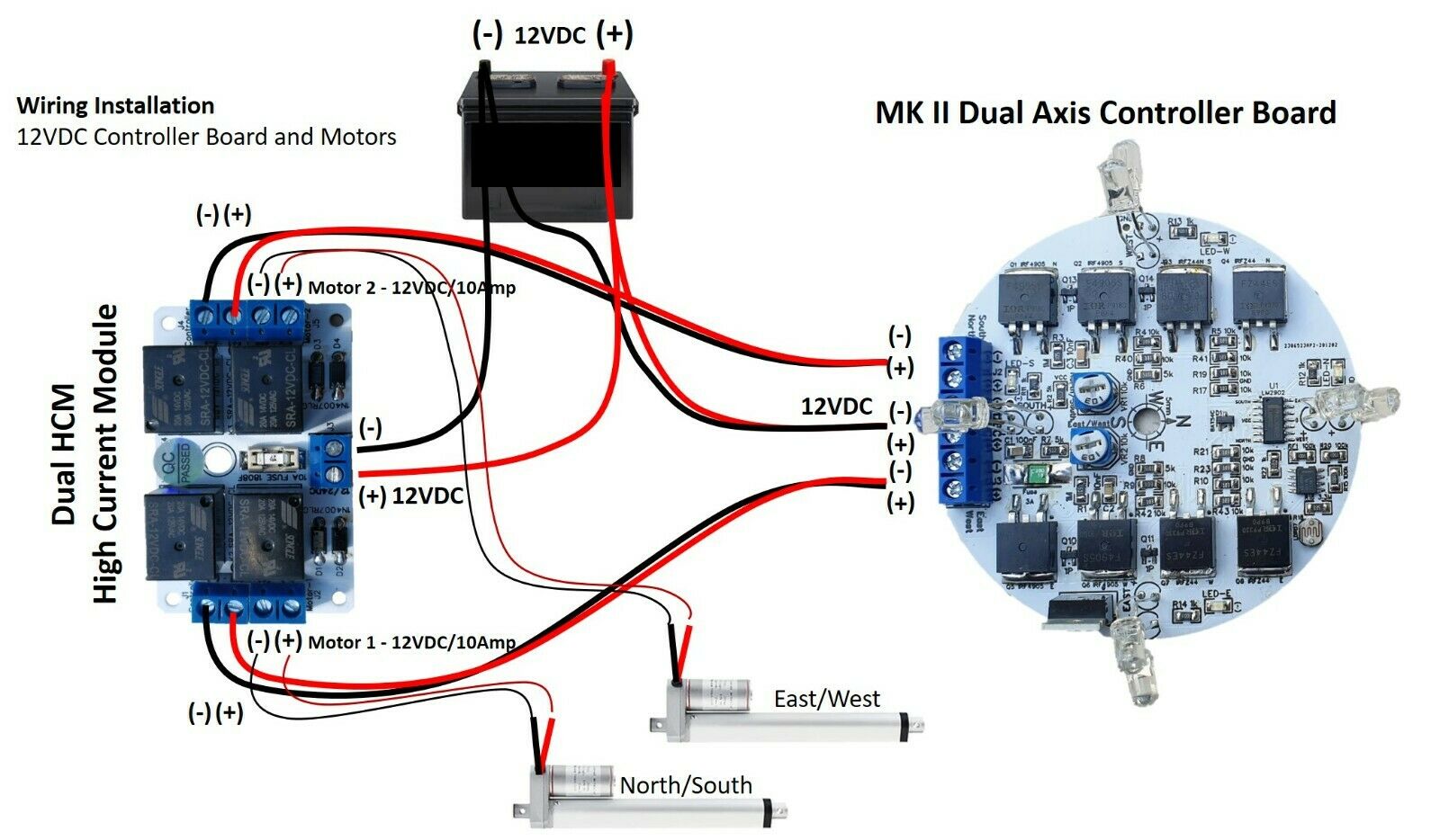
The Sun Tracking Controller is powered by using DC 12V +/-20%. The voltage source can be for example a car battery, Power Supply, an array of batteries etc. A good practice is to add a fuse in
series
to the power line of a 3Amp in order to protect the controller board from over current. MK II controllers has on board
3Amp
electronic fuse
If you use high current load (motor) I provide three solutions for 10 Amp load.
1. Single Channel
High Current Module with or without on board 10Amp fuse
2. Dual Channels
High Current Module
with on board replaceable 1808F 10Amp fuse
3. 10Amp 12VDC Single Axis Solar Panel Sun Tracking Electronic Linear Control Board
For more
details
Please visit my Store:
http://www.ebaystores.com/hobbizelectronics
6. What in the Box
1.
1x Controller Board per order
2.
2x Plastic Spacers to allow optimal assembly of the board in a camera dome, not including the screw (only for the dual axis controller)
3.
The box
don’t
include an enclosure dome nor the Jar made from PET
I made special design to
miniaturize
the PCB form factor so it can fit a off the shelf 150mil Jar with 81mm/3.2in inner diameter, y
ou can use your own DIY Jar
.
Please visit my store for Jar PET Kit, a bundle with installation hardware, make it easy for your project.
Now my Dual and Single Axis Controller boards
enhanced++
design can be installed in a 150mil Jar.
Jar Dome Sealed Enclosure Single Axis Solar Sun 12VDC Tracking Controller Board
http://www.ebay.com/itm/Jar-Dome-Sealed-Enclosure-Single-Axis-Solar-Sun-12VDC-Tracking-Controller-Board-/333533559105?hash=item4da8263941
7. Payment
·
Please make sure your eBay address is correct
·
Now with Payoneer we accept Credit/Debit Cards, PayPal etc...
·
We are not responsible for any tax or duty incurred by overseas customs. Please see what is right for you before purchasing.
8. Feedback
·
Feedback is extremely important to us and eBay, if you are satisfied with our transaction, please take a moment to leave Positive Feedback
·
YOUR Satisfaction is our #1 Priority
!
9. Contact Us
·
If you have any concerns about your order, PLEASE contact us through eBay message or e-mail to resolve any issues BEFORE leaving a natural rating, negative feedback or opening a dispute. We will reply within 2 business days (public holidays not included)
10. FAQ
1.
I have just installed the sensors, full of sun but they are doing mostly nothing.
Check the wiring relative to the motor physical location and follow the sanity testing paragraph #3.
2.
How to calibrate the potentiometers?
2.1.
What is the best orientation of the photosensors?
2.2.
Cannot adjust it accurately and it does not find the sun as it should?
2.2.1.
Calibrating the LED East West Angle
Skew (left/right) lightly the LEDs such that each LED will cover more angle, this will ensure smoother operation.
URL:
https://i.ebayimg.com/00/s/MTAzMFgxNDQw/z/6gUAAOSw8OVfAvVt/$_57.JPG?set_id=8800005007
It's an iterative process, where you adjust the LED angel slightly each time until you are satisfied with the results
2.2.2.
Calibrating the LED North South Angle
Skew (up/down) lightly the LEDs such that each LED will cover more angle, this will ensure smoother operation.
It's an iterative process, where you adjust the LED angel slightly each time until you are satisfied with the results
2.2.3.
Calibrating the Potentiometer
In a dark room (natural light) or no specific light source directed to the Photo LED sensors (clear 5mm LED), the output voltage on the motor connector should be zero and all the SMD (Blue can be other color) LEDs are OFF. If not, turn the potentiometer clockwise till the potentiometer stops rotating, the relevant SMD LED will turn ON. Verify no light source directed to the Photo LED sensor and now start to turn the potentiometer anticlockwise very slowly until the relevant SMD LED turn OFF and the voltage on the relevant motor connector is zero. After this procedure use a flashlight to check again, it should work much better. You may need to do so several times until balance in the sensitivity is achieved.
3.
How to verify the correctness of controller operation - Some Sanity Testing.
3.1.
Use a flashlight to directly illuminate the clear 5mm photo LED sensors and see if it moving east and west and or north and south?
3.1.1. Illuminate West Photo LED, SMD (Blue) LED is ON, if you connected the linear motor, it will pull in or the PV move west
3.1.2. Illuminate East Photo LED, SMD (Blue) LED is ON, if you connected the linear motor, it will push out or the PV move east
3.1.3. Illuminate South Photo LED, SMD (Blue) LED is ON, if you connected the linear motor, it will pull in or the PV move south
3.1.4. Illuminate North Photo LED, SMD (Blue) LED is ON, if you connected the linear motor, it will push out or the PV move north
3.2.
Check the wiring connection. The +/- of the linear motor is set such that for
3.2.1.
East to West the actuator will pull-in.
3.2.2.
In the morning, it will go West to East and it will push-out
3.2.3.
South to North the actuator will push-out.
3.2.4.
In the morning, it will go North to South and it will pull-in
3.2.5.
Its common that the East to West actuator is installed in the right side when you look at the panel in front of you. In this case you should swap the motor +/-.
3.3.
Check the DC power line and motor connectors wiring connection.
3.3.1.
12VDC for 12V Controller
3.3.2.
24VDC for 24V Controller
3.3.3.
The +/- of the DC power line is protected from reverse polarity
3.3.4.
Verify the power line is connected to the DC connector only. Connecting the DC power line to the Motor Connector will damage the board beyond repair. In this case the warranty will be null and void.
3.3.5.
The caption on the connectors is very clear and show what is the Motor connector and what is the DC power line connector. Furthermore, please consult with the technical information attached in the list or contact us for support.
3.3.6.
The +/- of the motor connector will not harm the controller, yet polarity/direction of the motor will be swapped, e.g. instead of pull, it will push or rotate anticlockwise instead of clockwise.
4.
Sensor installation
4.1.
Where to install the Sensors Board?
The sensors board must be installed on the moving PV Panel
4.2.
What is the orientation?
The sensors board should be installed horizontally to the panel and perpendicular to the compass directions and above the PV panels such that it will see the sun without obstructions
. Use the compass bearing caption on the board
4.3.
How to protect the board from rain, dust?
Use a Dome, Jar any transparent sealed enclosure.
4.3.1.
Transparent enclosure material
4.3.1.1.
Glass is the best, yet its fragile and heavy
4.3.1.2.
Acrylic with UV resistance, super transparent
4.3.1.3.
PET - Poly Ethylene Terephthalate, strong, fully recyclable and fair resistance to UV
4.3.1.4.
ABS, Polycarbonate are OK as long as they are UV treated. If not, they will deteriorate and be milky/yellowish over time
4.4.
Where to find an enclosure?
4.4.1.
DIY using a honey/jam Jar made from Glass, cosmetic Jar PET. The inner diameter of the Jar opening should be at least 81mm and with metal lid for grounding and longer life survival.
4.4.2.
DIY using security camera box or a dummy camera box with the transparent dome. Two caveats, the dome should be UV resistance otherwise it will become opaque/milky over time. Use some silicon glue for sealing.
4.4.3.
There are multi links on eBay/AliExpress for UV resistance " 4 Inch Indoor / Outdoor CCTV Replacement Acrylic Clear Monitoring Camera Cover Dome Housing"
4.4.4.
You can find on my eBay Store a DIY Jar PET - Poly-Ethylene Terephthalate plus hardware installation kit
4.5.
I'd like to start with just one axis system
and then add a second axis afterwards. Is this possible by just leaving the North / South clamps on your board empty?
4.5.1. Yes, each axis works in parallel and independently
4.5.2. Just connect the right axis to the right actuator and it will work fine
4.6.
Installing the controller board
. What should I do with the plastic spacer and washer in the box
4.6.1. The spacer shall be installed under the board to isolate it and prevent potential electric short
4.6.2. The washer shall be installed between the PCB and the screw head or nut to prevent damage to the board traces when tightening it
4.6.3. When handling the controller board please have ESD protection in place
5.
Limit switches, why I need it? How I install them?
The limit switches prevent from the motor to
exceed e
nd
of move for linear motors or prevent 360 rotation of axial motors, thus preventing damage, overheating and burning of the motor or the controller.
5.1.
Most if not all linear motor actuator has a build in limit switches no precautions are needed. However axial motors usually do not have such and do need limit switches
5.2.
Wiring diagram URL:
https://i.ebayimg.com/images/g/sk8AAOSw5Mle87~3/s-l1600.jpg
5.3.
Tip: Select microswitch and diode according to the expected current of the motor. High current needs stronger diode and high rated microswitch
5.4.
You can use my novel relay module with limit switches fully integrated, simplify interconnection
https://www.ebay.com/itm/334033915094?hash=item4dc5f90cd6:g:caQAAOSwLVlgwH2U
https://www.ebay.com/itm/334033962574?hash=item4dc5f9c64e:g:ZRYAAOSw~s5gwJKG
6.
Will this work for stepper motors, brushless, or actuators?
The sun tracking controller support DC voltage motors such as
6.1.
Linear Motor or an Actuator that move In and Out
6.2.
Axial Motor that rotate 360 clockwise or anticlockwise
6.2. The sun tracking
controller does not support Stepper Motors that need pules to rotate clockwise or anticlockwise.
7.
West to East Sensor
The controller support returning to east at the end of the day after the sunset automatically
7.1.
It is highly recommended that the controller will not be installed under or near by a lantern / street light. This may prevent the sensor to work properly.
7.2.
The default setup of the sensor is to deep night i.e., very low light. The LDR (Light Dependent Resistor) is calibrated using a 3.3MOhm. To trigger the move to East earlier, need to adjust the 3.3MOhm to lower value. The trade off is false alarm where it may trigger too early due momentarily conditions such as a dark c
l
oud, shadow from nearby buildings, dark gray sky etc…
8.
Tips to Improve Durability
Is there something in your design that would make it more durable? First, all new MK II have an Over Current, Over Voltage and Reverse Voltage Protection. With all the electronics baking under a glass enclosure midsummer, would your unit fail also due to too much heat in a short time. Any thoughts would be appreciated.
8.1. Would it help to just remove glass dome during our long dry season to get air flow on electronics? No, it will bring other issues like dust, dew, bird poop etc…
8.2. Adding a hole at the lid bottom side for ventilation can help, somewhat
8.3. Ultraviolet due to direct sun will cause over time degradation to components, and plastic parts like connectors, LEDs etc…
8.3.1. A good option is to use the Sensor Board Only, such that the controller can be placed away from the direct sun
8.3.2. Can put a cardboard that will cover/shadow the electronics from direct sun. This will prolong the life of the controller. Do not cover the Photo LEDs or the LDR
8.4. Another thing that you can do, is to flip and place the board upside-down such that the back side will face the sun (need to put the LDR and Photo LEDs at this side too)
9.
Where do I find Fuse for my controller or relay module?
9.1. I have checked the relay module and it appears the XX Amp fuse is blown. Is this item something I can find in the U.S.?
9.2. First check why the fuse was triggered, are the wiring correct? Is the load is too high? was there any electrical short?
9.3.
You need to look for "1808 SMD Ceramic Fuse XXA" on eBay/AliExpress (I'm using slow blow from Littlefuse)
Shipping
We have free shipping on some of our products, mainly we ship by economy domestic and international, in case you have a special request please send us a message before buying the product
We only ship to verified PayPal addresses worldwide, if you need to change the address please do it before purchasing the product.
Your order will be shipped within 1 to 3 business days once your payment received. Will ship registered mail with tracking number. The shipping to USA and other international destinations usually takes 15 -25 business days to deliver. Still, if from some reason that is out of my control you haven’t received it after 40 days business days, PLEASE contact us, we will provide you a solution.
If you have any concerns about your order, PLEASE contact us through eBay message or e-mail to resolve any issues BEFORE leaving a natural rating, negative feedback or opening a dispute. We will reply within 2 business days (public holidays not included).
We are not responsible for any tax, or customs duty incurred at foreign customs, please look what right for you before buying.
Returns
We have the policy of Returns and a refund will be given as money back or item exchanged within 30 days of delivery. For this, the article must arrive in the same conditions in which you received it. The buyer is responsible for the cost of shipping.
About us
Welcome to your eBay "Hobbiz Electronic by BONLAF Store", there are wide variety of items that wait for you, new and used in excellent condition, items for your hobbies that will support your DIY projects you eager to complete. You can find Top Quality Proto Breadboards Kits, Metal Detectors Assembled Kits, Affordable Price Sun Tracking Controllers for Solar Energy harvesting and more opportunities for you. Customized orders are welcomed. Our products sell well in North America, Latin America Europe and Middle East. Our company insists on the principle of "Continuous Improvements, Innovation the top quality and competitive price".
We know that we are not the only ones, so we decided to do it in the best way and thus achieve your satisfaction, which is our reason for being here.
Join Our Exclusive Newsletter For Up To Date News, Special Offers And New Arrivals
Sign up Now
Shop Categories
Metal Detectors
Solar Panel Sun Tracking Cntrl
Proto Breadboard
New Arrivals
Others
Quick Links
Feedback
Add to Favorite Seller
Shop info
Home
About us
Returns
Delivery
Contact Us
Get in touch with us
Hobbiz Electronics
Felix Barmoav
2/2 Iben Gabirol
Rishon Leziyyon, Israel 7548102
Israel
Payment info
Copyright 2019
Hobbiz Electronics.
All Rights Reserved
